A/D 変換 (Arduino IDE + ESP ボードマネージャ)
サーミスタとは
サーミスタは温度によって抵抗値が変化する素子である. 抵抗値は温度の関数として以下のような近似式で表現できる.
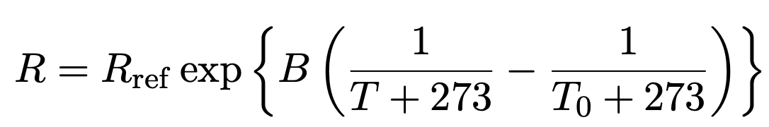
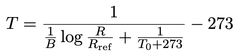
但し, R と Rref はそれぞれサーミスタの抵抗値と基準となる抵抗の抵抗値, B はサーミスタの種類によって決まる定数, T と T0 はそれぞれ温度と基準温度, である. 上式を温度について解けば以下のように書ける.
上式中の定数の値であるが, 学習ボードでは
- Rref = 10.0 kΩ
- T0 = 25 ℃
- B = 3435
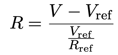
となっている. あとは抵抗値 R の値が計測できれば温度が計算できる. 抵抗値 R を計算するために, 教育ボードでは以下のような回路が組まれており, Vref の値からオームの法則より R が得られるようになっている (図はITOC のチュートリアルより引用).
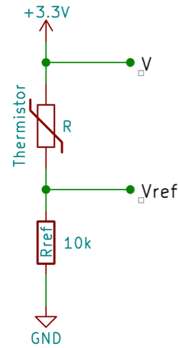
Vref を求めるプログラムを書けば, Vref より R が得られる.
ESP32 マイコンには ADC(アナログ・デジタル・コンバータ)が搭載されており, Vrefの値を簡単に計測することができる.
プログラムの書き方
Language Reference の "Analog I/O" の項目を参照して欲しい. 基本的に analogRead 関数を使う
気になること.
公式ドキュメントのどこに書かれているか見つけられていない事項.
- analogRead の読み取り値は 0 ~ 4095 の範囲?
- 電圧計測の範囲は 0 ~ 3.6V?
サーミスタ温度計
プログラムの作成
これまでと同様に, スケッチ例を利用する.
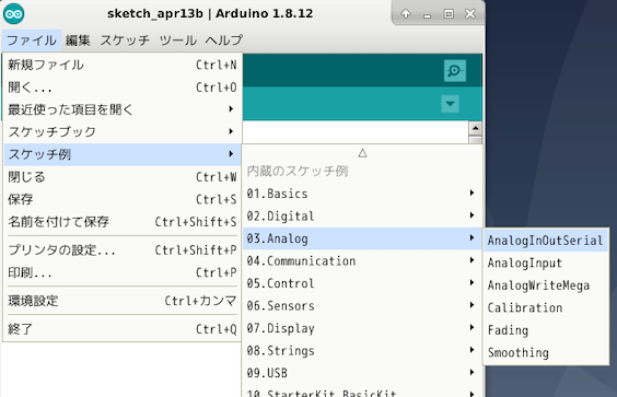
スケッチ例 (AnalogInOutSerial) を簡略化したものを以下に示す.
1  // These constants won't change. They're used to give names to the pins used:
2  const int analogInPin = 39;  // Analog input pin that the potentiometer is attached to
3
4  int sensorValue = 0;        // value read from the pot
5  int outputValue = 0;        // value output to the PWM (analog out)
6
7  void setup() {
8    // initialize serial communications at 9600 bps:
9    Serial.begin(9600);
10 }
11
12 void loop() {
13   // read the analog in value:
14   sensorValue = analogRead(analogInPin);
15   // map it to the range of the analog out:
16   outputValue = sensorValue * 3600.0 / 4095.0; //単位はミリボルト
17
18   // print the results to the Serial Monitor:
19   Serial.print("sensor = ");
20   Serial.print(sensorValue);
21   Serial.print("\t output = ");
22   Serial.println(outputValue);
23
24   // wait 1 sec
25   delay(1000);
26 }
- 2 行目: Vref を計測するために利用するピンの GPIO を指定. 教育ボードでは GPIO 39 である.
- 9 行目: 計測した結果をシリアルモニタに表示するために, シリアル通信の速度を 9600 に設定.
- 14 行目: 無限ループ (loop 関数内) で analogRead() 関数で計測.
- 16 行目: analogRead の読み取り値は 0 ~ 4096 (12 bit) であるため, 最大電圧 3.3 V に比率 (analogRead の読み取り値 / 読み取り値の最大値の 4096) を掛け算することで電圧値 Vref [mV] が得られる.
- 19-22 行目: シリアルモニタへの出力.
次に, 得られた Vref から抵抗値を計算し, さらに温度に換算する関数 calc_temp を追加する.
1  // These constants won't change. They're used to give names to the pins used:
2  const int analogInPin = 39;  // Analog input pin that the potentiometer is attached to
3
4  int sensorValue = 0;        // value read from the pot
5  int outputValue = 0;        // value output to the PWM (analog out)
6
7  int calc_temp(int voltage){
8    float B = 3435.0;
9    float To = 25.0;
10   float V = 3300.0 ;
11   float Rref = 10.0 ;
12   float Temp = 1.0 / ( 1.0 / B * log( (V - voltage) / (voltage/ Rref) / Rref) + 1.0 / (To + 273.0)) - 273.0;
13   Serial.print("Temp = ");
14   Serial.println(Temp);
15 }
16
17 void setup() {
18   // initialize serial communications at 9600 bps:
19   Serial.begin(9600);
20 }
21
22 void loop() {
23   // read the analog in value:
24   sensorValue = analogRead(analogInPin);
25   // map it to the range of the analog out:
26   outputValue = sensorValue * 3600.0 / 4095.0; //単位はミリボルト
27
28   // print the results to the Serial Monitor:
29   Serial.print("sensor = ");
30   Serial.print(sensorValue);
31   Serial.print("\t output = ");
32   Serial.println(outputValue);
33
34   calc_temp(outputValue);  //追加
35
36   // wait 1 sec
37   delay(1000);
38 }
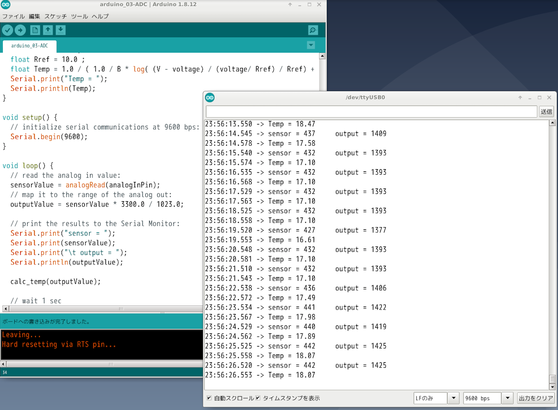
- 7 ~ 15 行目, 34 行目に温度計算と表示を追加されている. 基板の定格電圧は 3.3V なので, V = 3300 にしている.
シリアルモニタを表示すると, 温度が表示される.
課題
LED, スイッチ, サーミスタ温度計を使ったプログラムを作成せよ.
- 温度がある閾値を超えたら LED を点灯させてみよ. (サーミスタ温度計を触ると)
気になること
- Arduino IDE で analogRead した値が, esp-idf や micropython の場合と微妙にずれる. とある日において, 前者が 1840 に対して後者が 1865 程度 (相対誤差 1.5% 程度).
- Arduino IDE で計測できる電圧の範囲は? 3.3V? 3.6V?
- ESP-IDF と同じ仕組みなら 3.6 V かなぁ?
- 温度に直したときは 3.3 V の方がそれっぽいのだが.